|
 Although some claim that
the Nixie tube ("Numerical Indicator eXperimental") was invented in
1952 by the Haydu brothers, this does not mesh with the known history
of gas discharge tubes.
Although some claim that
the Nixie tube ("Numerical Indicator eXperimental") was invented in
1952 by the Haydu brothers, this does not mesh with the known history
of gas discharge tubes.
Click here for some commentary
on the history of the Nixie tube.
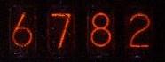
The standard Nixie display consists of ten
individual digit wires inside a vacuum tube. Applying a small
amount of current at a relatively high voltage causes the wire
to glow, illuminating the digit.
Nixies have long since been replaced by light-emitting diode (LED)
and liquid crystal (LCD) displays, but I am interested in collecting
and preserving these classic pieces of electronic history.
If you have any Nixie tube devices or drivers just gathering dust
that you'd like to get rid of, please
send me an e-mail and
we can work something out!
I'd also love to find actual Nixie clocks, whether test equipment
(such as the
Hewlett-Packard HP 571B)
or commercially made units.
|
[Excerpted from Fundamentals and Applications of Digital
Logic Circuits by Sol Libes, 1975, Hayden Book Company.]
(Click on either Figure for a larger version.)
 Gas-Discharge Display
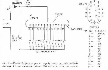
More commonly referred to as Nixie, the gas-discharge tube was
introduced by the Burroughs Corporation in 1955. It is basically
a cold-cathode tube (Figure 9-14) with separate cathodes in the
shape of characters. When a sufficient potential is applied
(approximately 175 volts) between the selected cathode and plate,
the gas surrounding the selected cathode is ionized and glows.
Other types of gas-discharge displays are available having glow-bar
segments to form in-plane characters and also cathode rods to
illuminate a printed or cut-out character.
|
 Figure 9-15 shows how a typical gas-charge display tube is driven
from TTL logic. IC-7490 is a decade counter with parallel BCD
output and serial count input. The overflow from the counter is
used to operate the next more signficant digit display. The BCD
counter output is fed to a quad bistable latch (IC-7475) which
acts as a memory storage. The count is stored in the IC until a
strobe pulse allows the output of each latch to change. This
prevents the display from being a blur of changing numbers. The
BCD output of the latch is decoded by IC-7441 (BCD-to-decimal
decoder/driver) to a one-of-ten decimal output. The IC also has
high-voltage driver transistors to drive the cathodes of the tube.
Figure 9-15 shows how a typical gas-charge display tube is driven
from TTL logic. IC-7490 is a decade counter with parallel BCD
output and serial count input. The overflow from the counter is
used to operate the next more signficant digit display. The BCD
counter output is fed to a quad bistable latch (IC-7475) which
acts as a memory storage. The count is stored in the IC until a
strobe pulse allows the output of each latch to change. This
prevents the display from being a blur of changing numbers. The
BCD output of the latch is decoded by IC-7441 (BCD-to-decimal
decoder/driver) to a one-of-ten decimal output. The IC also has
high-voltage driver transistors to drive the cathodes of the tube.
|
| |
|
The following is taken from Circuits for Digital Equipment by
C. J. Dakin and C. E. G. Cooke (1967):
Where character readout is required multi-cathode gas discharge tubes are used.
One method of construction is to make each cathode the shape of the character
to be displayed. For example one tube might have 10 cathodes in the shape of
numerals 0 to 9. To cause the required cathode to glow a suitable voltage
is applied between the anode and the selected cathode.
Typically the discharge will strike at about 80V and burn at about 60V.
The circuits to drive such tubes must therefore be able to supply such
voltages.
A suitable circuit is shown in Fig. 16.9. Note that when Tr1
is off the collector does not rise to +150V but is 'caught' at about +80V
provided one of the other cathodes is energized.
The disadvantages of this type of indicator are:
- The characters do not lie in the same plane.
- The number of characters in one tube is limited to about 12.
The advantages of this type of indicator are:
- The characters are well-shaped.
- The characters are bright and can be large. (Tubes with characters
up to 3 in high are available.)
| |
|
- 7441 - Early BCD Nixie driver
This part was also sold by Radio Shack as catalog number 276-1804.
- 74141 - BCD Nixie driver
- 8T - Signetics Nixie Driver:
Click here for the datasheet.
| |
|
ARTICLES ABOUT DISPLAY TUBES
|
|
 Electronics hobby magazines from the 1960's and 1970's occasionally
ran articles on Nixie tubes and other cold cathode display
devices. I've begun to scan the articles
from old magazines and make them available.
Electronics hobby magazines from the 1960's and 1970's occasionally
ran articles on Nixie tubes and other cold cathode display
devices. I've begun to scan the articles
from old magazines and make them available.
Click here to view
an index to several
construction projects from the magazine Radio-Electronics.
| |
|
 In 1969 Signetics published an application memo entitled
Multiplex Operation Of Nixie® Tubes Using Signetics'
Complex Arrays and Nixie Driver. It describes an approach
to minimizing parts count by using shift registers and Nixie
drivers to multiplex a set of Nixie tubes.
In 1969 Signetics published an application memo entitled
Multiplex Operation Of Nixie® Tubes Using Signetics'
Complex Arrays and Nixie Driver. It describes an approach
to minimizing parts count by using shift registers and Nixie
drivers to multiplex a set of Nixie tubes.
You can read the note by clicking
here.
| |
|
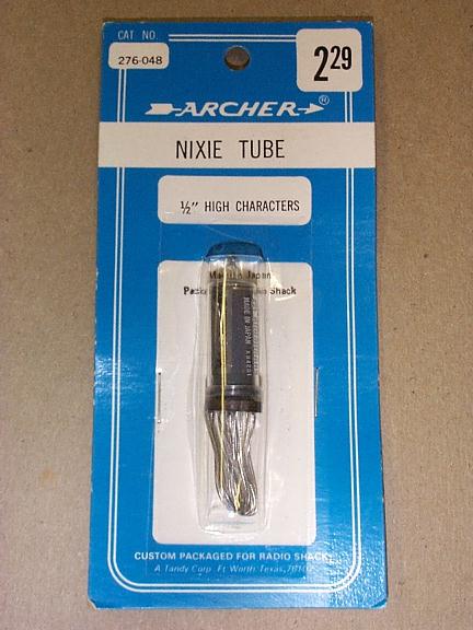
RADIO SHACK 276-048 NIXIE NUMERICAL INDICATOR
|
|
 Yes, it's true, you used to be able to purchase nixie
tubes at your local Radio Shack. I've got a few of these
tubes in their original packaging.
Yes, it's true, you used to be able to purchase nixie
tubes at your local Radio Shack. I've got a few of these
tubes in their original packaging.
From the data sheet:
The Radio Shack #276-048 is a cold cathode, side viewing numerical
indicator tube. It displays the numerals 0 through 9 and has two
internal, independently operable decimal points located to the left
and right of the numeral. The desired numeral is lit when its
corresponding cathode is energized. The color of the display is
neon red. The brightness of the numerical indicator is dependent
upon cathode current, and the horizontal viewing angle is 100 degrees.
Click here to see a scan
of the datasheet.
| |
|
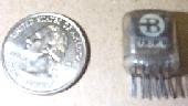
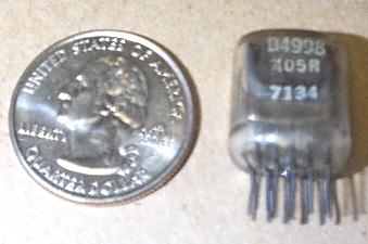
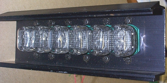
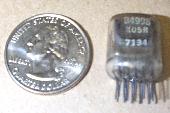 One of the smallest Nixie tubes is the Burroughs B4998,
a top-view design
One of the smallest Nixie tubes is the Burroughs B4998,
a top-view design
|
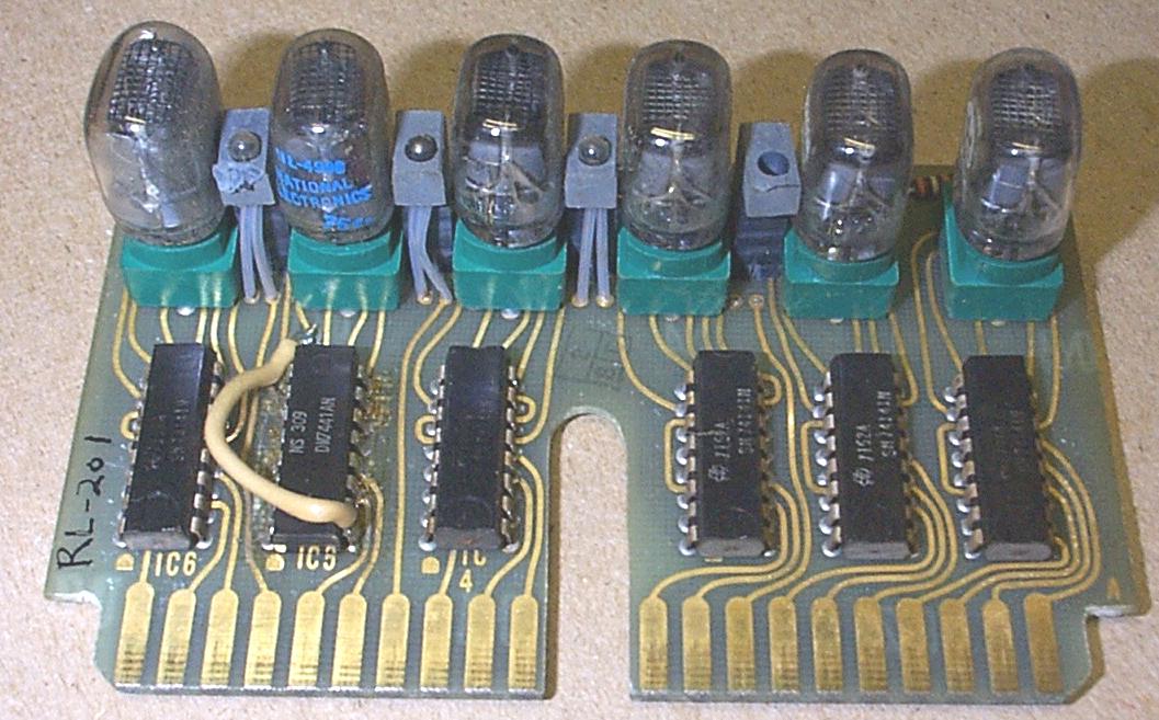
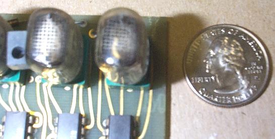
 I have a display module from an old piece of test equipment
that has six of these display tubes.
I have a display module from an old piece of test equipment
that has six of these display tubes.
|
| |
|
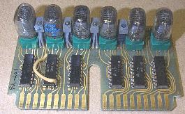
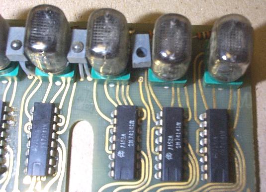
 I have four of these Nixie tube assemblies but I don't have any
documentation on the pinouts or even what equipment these were
designed for.
I have four of these Nixie tube assemblies but I don't have any
documentation on the pinouts or even what equipment these were
designed for.
From Stuart Walker:
I can tell you that the driver chip is a Fairchild 996079 sometimes called
a 9960 or 960, shortly after 1969 they became obsolete and were part of
a family of chips called CUL or Counter micrologic. They were peculiar in
that they took an inverse binary input and therefore needed the matching
transistor or IC, therefore the transistor is possibly a 995879 sometimes
called a 9958 or a 958, which was a decade counter and either available
in the 8 pin transistor package (to 5) or 14 pin dual in line package.
| |
|
ANOTHER NIXIE TUBE ASSEMBLY
|
|
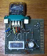
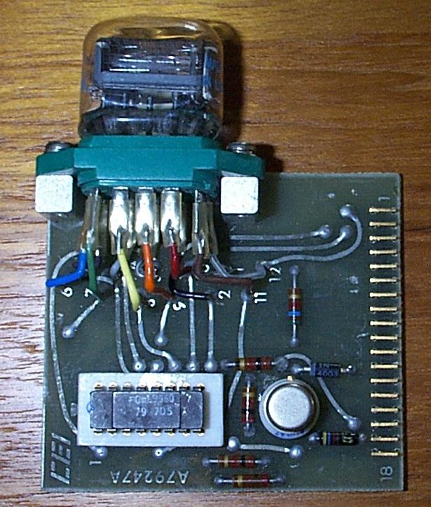
 I have one of these Nixie tube assemblies and I'm looking
for the pin-outs for the BIPCO 8806-3 Nixie driver/decoders
it uses.
I have one of these Nixie tube assemblies and I'm looking
for the pin-outs for the BIPCO 8806-3 Nixie driver/decoders
it uses.
You can see more photos and information by clicking
here.
| |
|
HEWLETT-PACKARD HP NIXIE MODULE
|
|
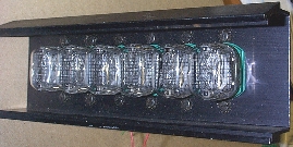
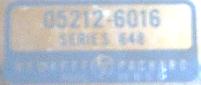 I have a handful of these HP Nixie boards, part number
05212-6016 Series 648.
I have a handful of these HP Nixie boards, part number
05212-6016 Series 648.
They have a very interesting decoder design using neon lamps
(hidden under the black lid just behind the Nixie tube).
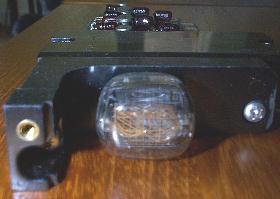 This is a description of the design from Tony Duell:
HP made a decade counter/display board where the counter
flip-flops were made from pairs of transistors in the conventional way (8
transistors on the board). These were controlled with diodes to count in
1242 (not 1248) BCD code.
The outputs of these counters drove 8 neon bulbs, and by varying the bias
applied, the state of the counter could be latched in the bulbs (that's
why this is relevant here). These bulbs were mounted inside a plastic
block on the PCB, and shone onto a thick-flim circuit of CdS
photoresistors. These were connected to form a binary to decimal decoder
to drive a nixie tube.
Inside [the block] there are 8 neons. From the top,
they are : C, C/, B/, B, D, D/, A, A/ (according to the manual). The neon
wires are soldered to the PCB. On top of the block is the thick-film LDR
array, and on top of that is a resistor network of 10 270k resistors. The
top wire of that goes to the +20V rail, the wires on the left go to the
nixie cathodes (there's a 270k resistor from each cathode to +20V). The
LDRs also connect to the cathodes. The bottom wire from the resistor
network is not used, but the pin it's connected to is the common of the
LDR array, and goes to -130V.
I can provide a pinout of the 15 pin card edge, but the signals may not
be too obvious without the complete service manual. Pin 1 is towards the
front (nixie tube) end
1 : -130V
2 :
3 :
4 : +170V
5 : Transfer Input (latch enable)
6 : BCD Output A
7 : Signal Input
8 : Gate Input (Not used?)
9 : BCD Output B
10 : Signal Output to next decade
11 : +20V
12 : Reset Input
13 : BCD Output C
14 : BCD Output D
15 : -15V

And from Dave Brown, regarding model numbers:
The DCAs (Decimal Counter Assembly) in those counters (5243 series, 5245
series) came in low and high speed versions. The -6016 is the normal low
speed 600kHz version used in most of the count positions and provides +1224
BCD output to the rear panel connector. The -6003 version is the option 03
variation of it that provided 1248 BCD output with the '1' state
negative.(as opposed to the -6002 which was the same but with '1' state
positive.)
This module was used in several pieces of HP test equipment,
including the 5245L frequency counters.
| |
|
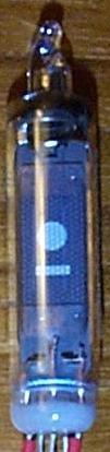
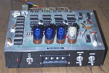 While not strictly Nixie technology, I have a four-digit
vacuum flourescent counter.
While not strictly Nixie technology, I have a four-digit
vacuum flourescent counter.
You can see more photos by clicking
here.
| |
|
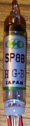 I have a dozen or so of these display tubes.
They have five wire leads.
The tube is marked SP8B, H.G.B. and were made in Japan.
I have a dozen or so of these display tubes.
They have five wire leads.
The tube is marked SP8B, H.G.B. and were made in Japan.
Does anyone recognize these tubes, and better, have a datasheet
for them?
I received the following information via e-mail:
Those are single-digit vacuum fluorescent displays. "ISE" is a subsidiary of
Noritake-Itron:
http://www.noritake-elec.com/itron/
Two wires are the filament connections (takes 1.5V, AC or DC),
one is the control grid,
and the remaining two are the symbol anodes (negative sign & overflow
indicator), which should be biased at +25 to +35 volts DC w.r.t. either
filament connection, through current-limiting resistors (10k or so).
| |
Equipment Listing
The following is a list of some Nixie equipment in my collection.
|
CALCULATORS WITH NIXIE DISPLAYS
|
|
- Casio 121-B, AS-L and FX-1
- Commodore 512
- Marchant I
- Monroe 610, 1655, 1710, 1770, 1775
- SCM Cogito 412, 414
- Sharp CS-363R
- Silver Reed SE-702
- Singer Friden 1114, 1118
- Sony Sobax ICC-400W, ICC-500W
- Remington-Rand 1259S
The main calculator page is
here.
| |
|
ANACONIC 390 DIGITAL MULTIMETER
|
|
Quantity one.
Uses four NL-840 type Nixies.
| |
|
FAIRCHILD 7050 MULTIMETER
|
|
FLUKE 8100A DIGITAL MULTIMETER
|
|
HEATHKIT IB-101 FREQUENCY COUNTER
|
|
HEATHKIT IB-102 FREQUENCY COUNTER
|
|
HEATHKIT IB-1100 FREQUENCY COUNTER
|
|
Quantity one.
You can read a review of this counter
here.
| |
|
HEATHKIT IB-1101 FREQUENCY COUNTER
|
|
HEATHKIT IB-1102 FREQUENCY COUNTER
|
|
Quantity one.
This is an eight-digit, 120 MHz counter.
You can read a review of this counter
here.
| |
|
HEATHKIT IB-1103 FREQUENCY COUNTER
|
|
Quantity one.
This is an eight-digit, 180 MHz counter with phase-locked multiplier.
| |
|
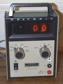
HEATHKIT IM-1202 DIGITAL MULTIMETER
|
|
|
Quantity five.
This is a neat little 2.5 digit multimeter.
|
|
|
The following two scanned pages are from the "TEST AND CALIBRATION"
chapter of the manual.
| |
|
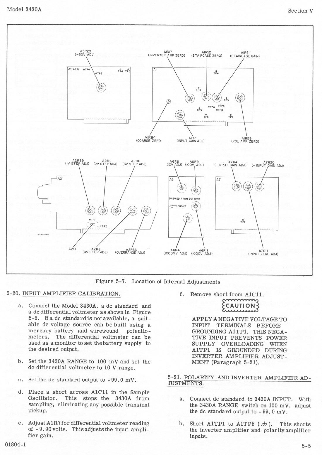
HEWLETT-PACKARD HP 3430A DIGITAL VOLTMETER
|
|
Quantity three.
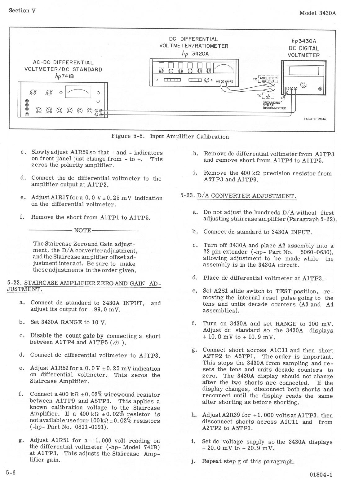
I've scanned parts of the Operating and Service Manual:
Calibration
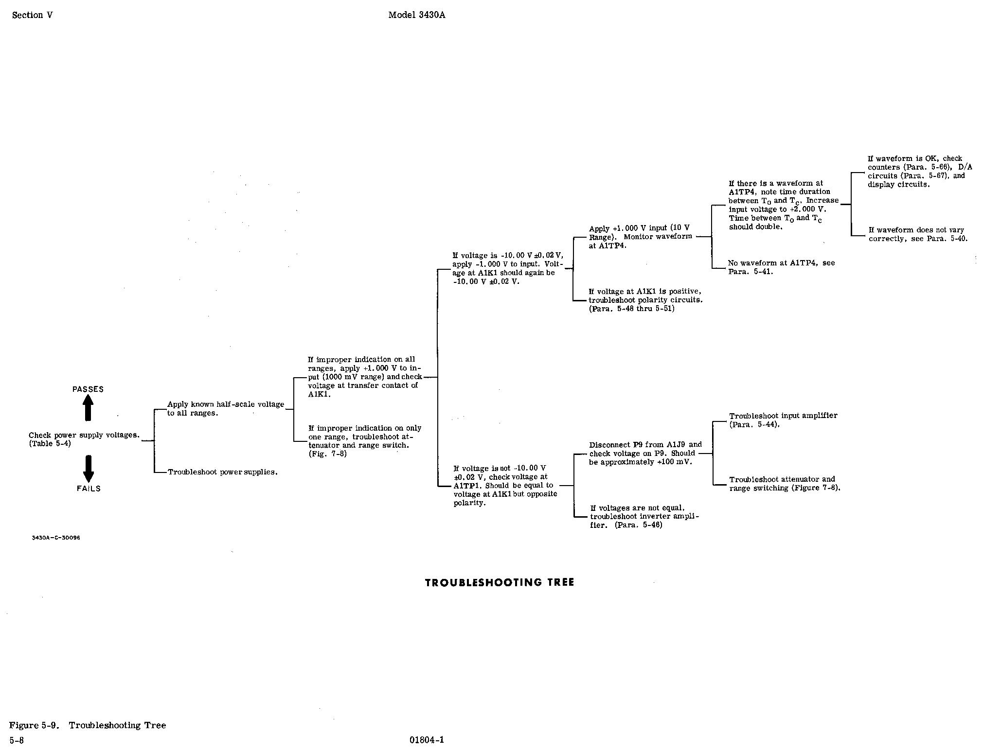
Troubleshooting
Diagrams
Schematics
These images are in PCX format. The original schematics come
as fold-outs in the service manual, and are too large for my
flatbed scanner. Each page has been scanned as two parts, a
left side and a right side.
Parts List
| |
|
HEWLETT-PACKARD 5245L COUNTER
|
|
Quantity one.
With 5252A Prescaler and 5265A Digital Voltmeter (plug-ins).
| |
|
HEWLETT-PACKARD 5246L COUNTER
|
|
Quantity one.
With 5253B Frequency Converter (plug-in).
| |
|
HEWLETT-PACKARD 5326 TIMER-COUNTER-DVM
|
|
HEWLETT-PACKARD 5332A PRESET CONTROLLER/COUNTER
|
|
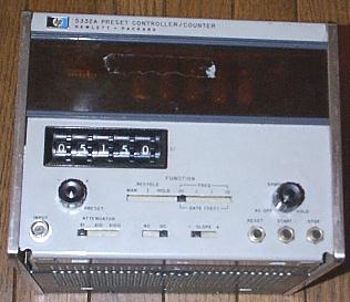 Quantity one.
| |
|
ITRON 650 FREQUENCY COUNTER
|
|
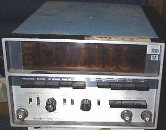 Quantity one.
| |
|
KEITHLEY 600 DIGITAL MULTIMETER
|
|
MONSANTO 100C COUNTER/TIMER
|
|
 Quantity one.
| |
|
MONSANTO 106A REVERSIBLE COUNTER
|
|
MONSANTO 1500A COUNTER/TIMER
|
| |
 Yes, it's true, you used to be able to purchase nixie
tubes at your local Radio Shack. I've got a few of these
tubes in their original packaging.
Yes, it's true, you used to be able to purchase nixie
tubes at your local Radio Shack. I've got a few of these
tubes in their original packaging.
 I have four of these Nixie tube assemblies but I don't have any
documentation on the pinouts or even what equipment these were
designed for.
I have four of these Nixie tube assemblies but I don't have any
documentation on the pinouts or even what equipment these were
designed for.
 I have one of these Nixie tube assemblies and I'm looking
for the pin-outs for the BIPCO 8806-3 Nixie driver/decoders
it uses.
I have one of these Nixie tube assemblies and I'm looking
for the pin-outs for the BIPCO 8806-3 Nixie driver/decoders
it uses.


![[Large]](heathkit-im1202-1.gif)
![[Large]](heathkit-im1202-2.gif)